|
|


 03-26-2011, 09:59 PM
any chance we can get a pictorial of this write up for us fellas that suck at wiring diagrams? I would literally send you a case of your favorite beer via the UPS man. thanks
 03-26-2011, 10:03 PM
and I only need pics of the wiring, basically which wires go where. No need to get into the whole transfer case swap stuff.
03-26-2011, 11:10 PM
Well, that's kindof the point of this whole bitch session... my wires may not look like your wires -- I'll try and get some pics nonetheless, but your colors and mileage may vary!
03-27-2011, 11:51 AM
yeah I hear ya, you know its bad when "Jeep" cant even get there diagrams straight. Maybe I'll get lucky and have the same wire colors that one of you guys had, or maybe I'll come across a whole new set of colors. That would be my luck, UGH! jeeps will be the end of us all... MARK MY WORDS
 04-01-2011, 02:31 PM
Dang, I need to to read this thing like six times to get it all. I swapped in a 231J With a JB conversions super short shaft and Need to wire it up to the speedo from the wheels, Because I am about 3 weeks a way from swapping the ford super duty axles in. Thanks guys for all the hard work!
04-06-2011, 05:35 PM
hey grin, not trying to pester you just checking on the status of a pictorial for this thread, thanks againOriginally Posted by grin

04-07-2011, 02:48 PM
sorry man, I keep thinking of it when I don't have time or am not near the jeep, and then forget when I do... I'll slap my own hand and get my ass in gear.
04-10-2011, 04:47 PM
Alright, for those who like picture books better than wiring charts... here's what it looks like on the rig. All nuts are full of RTV, and water tight:
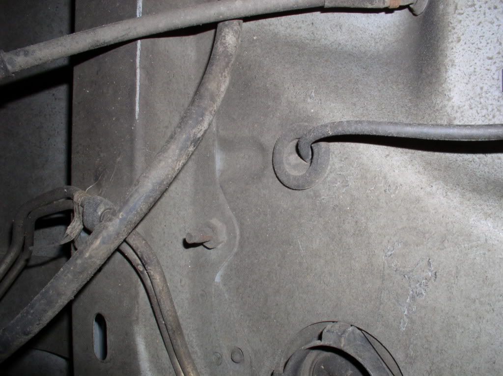
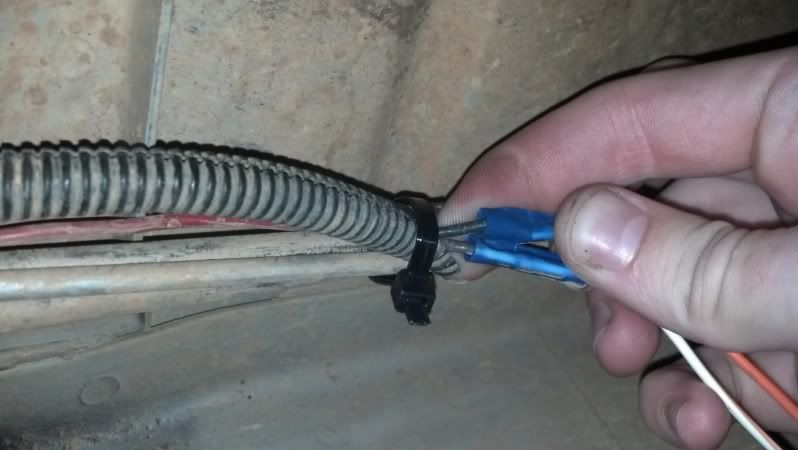
where the left-rear ABS sensor cable exits the chassis. Typically, it would run the other way, towards the rear axle, but we have it running to the T-Case:
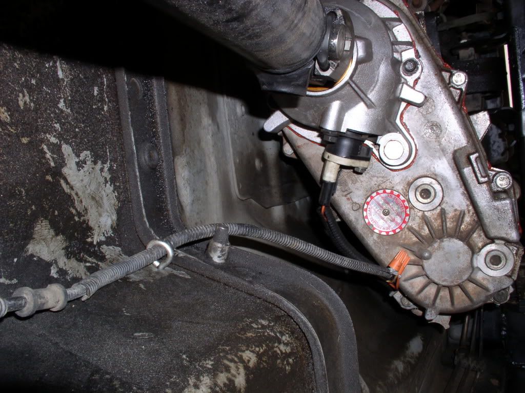
same cable running through an eye-bolt to the T-Case:
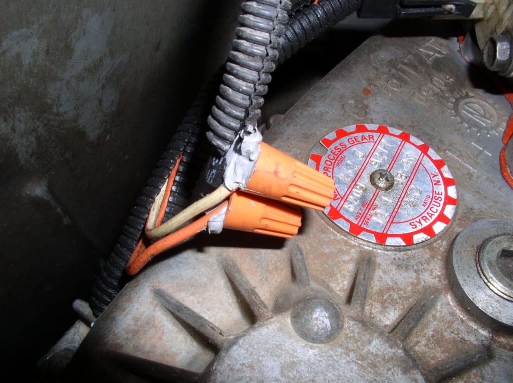
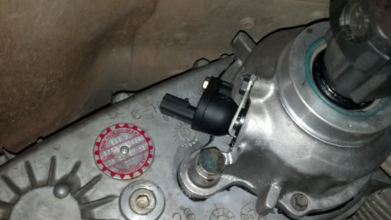
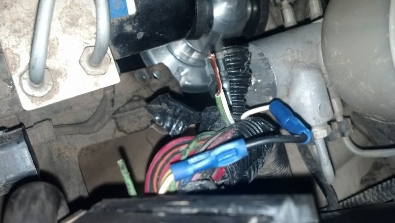
VSS sensor spliced in, orange on the VSS to black on the ABS cable, W/OR to the brown on the ABS cable:
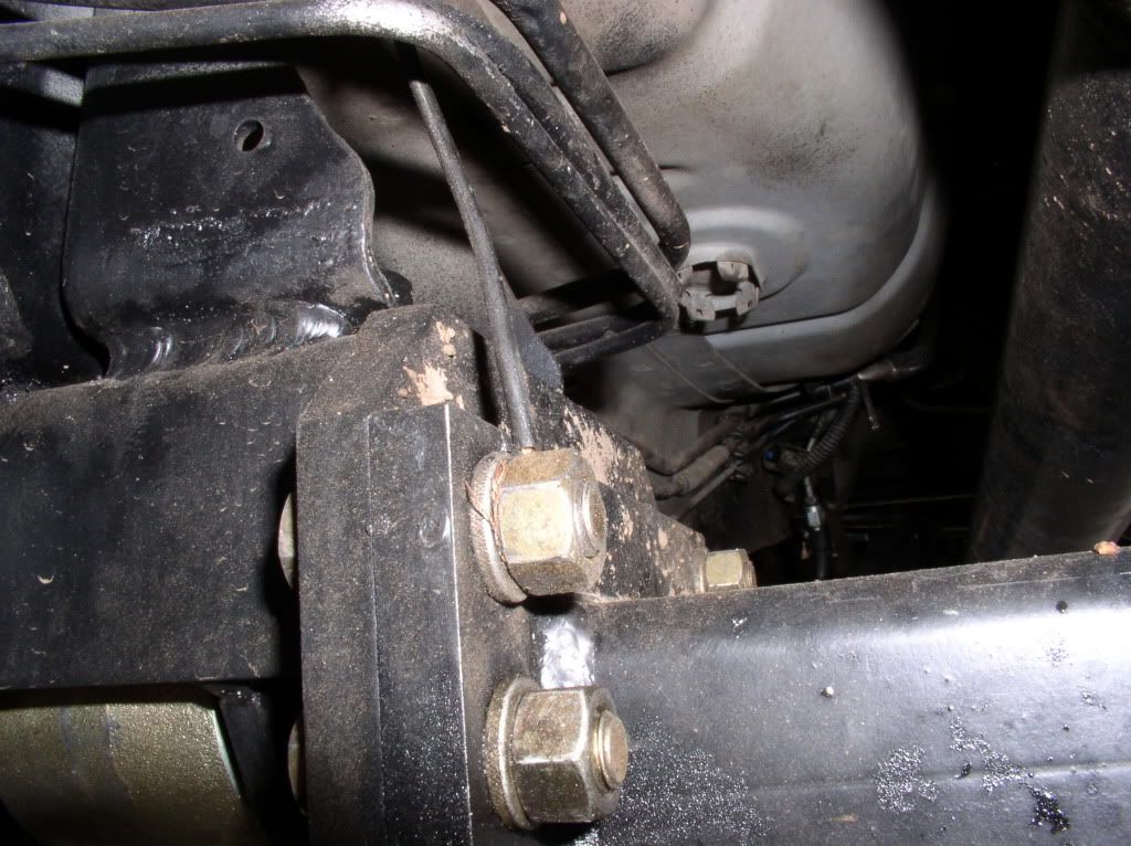
Ground from the VSS to the Chassis:
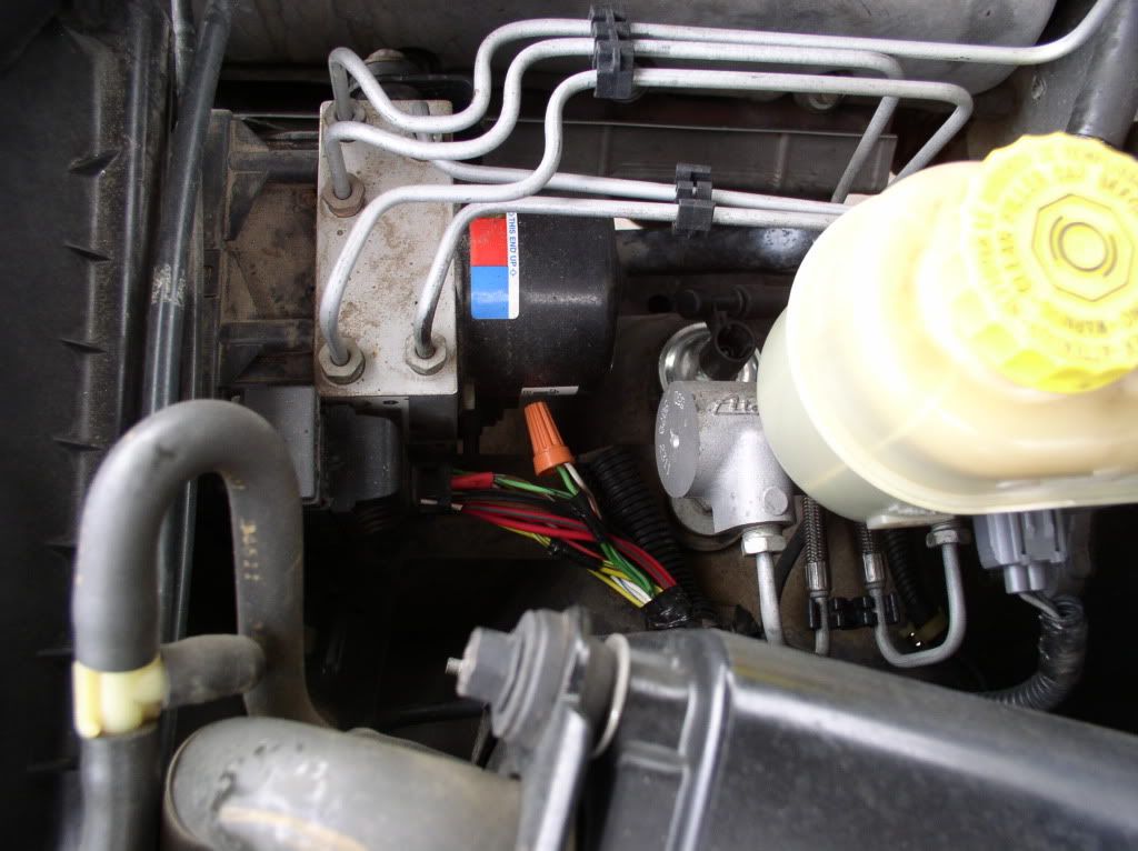
Under the hood, you want to find the ABS module, in front of the master cylinder:
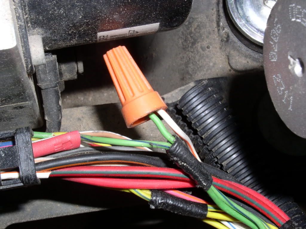
splice together the WT/OR and the LTGRN (at least in my application, as discussed, yours may be completely different):
and you're in business -- get the proper sized VSS gear from the chart in this thread, and enjoy!
Last edited by grin; 04-11-2011 at 06:23 PM.
 06-05-2013, 10:18 PM
OK, followed the thread to wire the speedo, still not working.
Speed sensor in with 41 tooth gear.
Orange to black
And white/orange to brown
And connected terminal 3 and 5 at the cab harness.
White/orange to green.
And still no signal.
From ground to orange I'm getting 5v
And ground to white/orange I'm getting 12v
And this is just key on not moving.
Where am I going wrong?
06-05-2013, 10:43 PM
I'd try switching from the green wire at the abs to the GN/BL wire... the wiring charts are inconsistent as to which goes where. check all your grounds as well...
06-05-2013, 11:02 PM
Ground is good. Checked that.
I'll try switching the white/orange and green to white/orange to green/blue.
07-12-2014, 01:19 PM
Sorry to bring back an old thread, but I have a quick question about something that was mentioned that appears to be unresolved. That, and I'm pretty much a tard when it comes to electrical stuff and need some help to finish up this portion of my build.
Question is, can the ABS pump be disconnected and removed completely (after the wire-splicing at the CAB harness), or does the ABS harness need to remain plugged into the ABS pump (though no longer working due to fuse/relay removal) in order to complete some sort of circuit?
Anyone?
 07-14-2014, 12:02 PM
Not sure about a WJ, but on my ZJ I pulled the whole pump/controller module.
01-04-2018, 04:04 PM
Sorry to bump an old thread, but the images seem to be gone (photobucket) and cannot be viewed. Can anyone post the images for the write up portion of this thread?
thank you

 01-04-2018, 08:40 PM
I put an extension on Firefox that allows the me to view them, I think there is one for Chrome as well. If you use Safari, you don't deserve to see any of this.
01-04-2018, 08:41 PM
Lol I'm using Chrome but I'll check out Firefox.
Sent from my SM-G900V using Tapatalk
01-04-2018, 08:55 PM
Ok, Firefox did nothing for me. The only images I cant see are the ones that were once on photobucket
Sent from my SM-G900V using Tapatalk
| « Previous Thread | Next Thread » |
| Thread Information |
Users Browsing this ThreadThere are currently 1 users browsing this thread. (0 members and 1 guests) |