|
|


 08-14-2010, 09:23 PM
Did the 231 swap, trying to get speedo working. No tone rings with the axle swap, so need to splice in the sensor in the 231. Should be simple enough, only question I have is how to handle the voltage.
WJ stock speed sensor is 12v supply, 231 sensor is 5v supply. From looking at the 231 sensor, I'm guessing it's nothing more than a metal gear rotating through an electric field, creating an oscillation in the voltage that is read by the PCM. I did some searching (yay google!) and found this appears to be what is called a "Hall sensor", and it sounds like these will work with a wide range of current: Technical crap that's mostly over my head
So- If I'm correct, I should just be able to hook up my 12v supply and be done with it.
And if I'm incorrect, I might cook my sensor and have to shell out some more $$$
I can always throw in a voltage converter (happen to have a 12v-5v converter sitting on my desk), but I don't think it's necessary.
Any input?
Last edited by FearTheDentist; 08-14-2010 at 09:27 PM.

 08-15-2010, 01:49 AM
Well i went ahead and winged it, works fine with a 12v input and is maybe a 20 minute job once you know what to do. I thought the signal would be way off and I'd have to use a Truspeed (sp?) but actually it's only reading about 10% over according to my GPS. Not sure which gear is in it right now, but I may be able to correct it just using a smaller gear. I'll do a quick write up once I'm confident this works long term.
I'd still be interested in any input on whether using 12v is a bad idea for any reason.
Last edited by FearTheDentist; 08-15-2010 at 01:51 AM.
 08-15-2010, 12:15 PM
Nice. Did it fix your stalling?
I don't think you are risking much by running the 12v signal. Any damage should be limited to just the sensor if it for some reason doesn't like the 12v.
Last edited by rstrucks; 08-15-2010 at 12:19 PM.
08-15-2010, 01:47 PM
I only took it for a brief test drive, but it didn't stall. I also pulled my TB- holy crap it was filthy. Cleaned it, pulled and cleaned the sensors, blew it all out- the idle is smooth again, dead steady at 1K rpm. We'll see about the shifting, but I think this was just a case of poor maintenance on my part rather than a bad sensor.
Funny thing is I've spent hours in recent months searching for a write-up on how to wire in the 231 sensor- I know I've seen it somewhere but damn if I can find it. Sat down to figure it out myself last night- 20 minutes with the FSM, 20 more for wiring and it works perfect. Go figure.
I was hoping I could splice the output from the speed sensor into the speed sensor signal input for all 4 wheels to the CAB and thus trick the ABS and get rid of the dash lights that way (not a big deal I know, just figured I'd give it a try). Didn't work at all, but when I spliced it in to the speed signal input to the PCM it worked fine.. One thing that occurred to me is the output from the 231 sensor is a square wave, I wonder if the output from the wheel sensors is a different wave form? I can't really see why else it wouldn't work on the CAB, but would to the PCM, unless maybe the CAB is smart enough to pick up that the input from all 4 wheels is all coming from the same sensor?
For anyone that is curious, the wiring is quite simple. The speed sensor on the 231 is 3 wires:
1) Orange- 5v (although I used 12v in my case)
2) Orange\White- speed signal to PCM
3) Dark blue (I think, it was dark)- signal ground (I just grounded to the chassis)
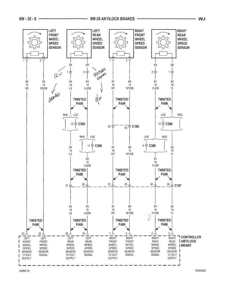
On the wiring to the existing wheel sensors, the solid wire is 12v, the striped is the return signal. I just used the existing wiring to the driver's rear sensor for power and signal, and ran a ground to the chassis. I cut the striped wire from the sensor at the CAB harness (Light green\blue I think), the speed signal out (dark green\yellow), and connected them. Viola!, works like a charm.
I'll do a real write up once I'm sure this is reliable, but it really is as simple as it sounds. Alternatively, you could splice into the wiring at the PCM harness (#2)- I forget which pin is the speed signal, and pin 31 is 5v supply, but I'm not crazy about messing around with this harness.
Last edited by FearTheDentist; 08-15-2010 at 02:05 PM.
08-15-2010, 10:28 PM
hall effect sensors are on or off, so rotational gates will obviously generate a square wave. Id find a switched 5v source for it.
03-08-2011, 12:25 PM
reviving an oldie-but goodie to seek some input from you guys that have done this... I've exchanged some PM with FeartheDentist, and that helped me get the concept, but I haven't got it working just yet.
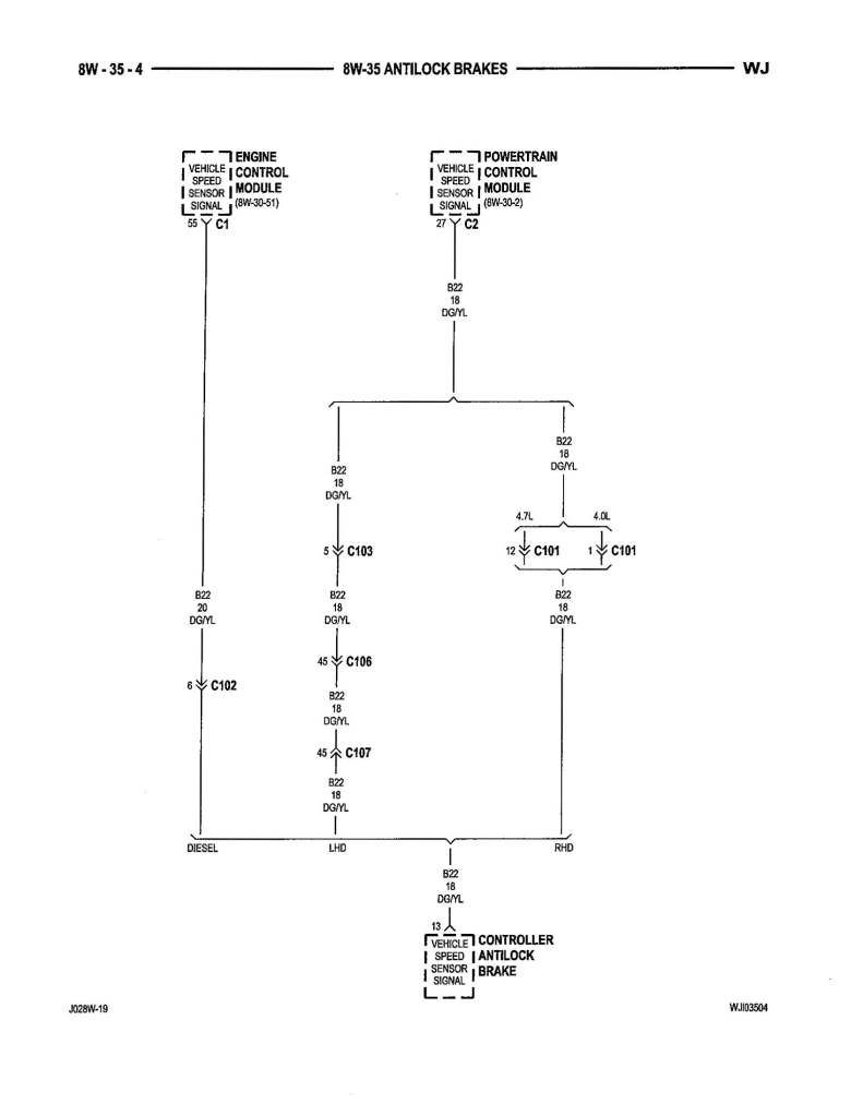
Here's the deal. I followed FeartheDentist's recipe above, but unfortunately my WJ has no DkGn/Yl wire to deliver the signal to the PCM/TCM/Speedo, as illustrated in this wiring diagram:
I found another wiring diagram indicating that it might instead be a Wt/Or wire delivering the speed info from the CAB to the PCM/TCM/Speedo, and that is a color of wire I DO have:
So currently, I have the BK wire from the left rear ABS (LtGrn later in the harness) hooked to the OR wire on my t-case VSS (12v power -- I will be reducing it to 5V with a radioshack part here shortly). I have the BR wire from the left rear ABS (LtGn/Bl later in the harness) hooked to the Or/Wt wire at the VSS (signal). I have the VSS ground grounded to the chassis. At the CAB (underhood), I disconnected the LtGn/Bl from the harness which should be the signal from the VSS, and connected it to the Wt/Or wire, also disconnected from the CAB -- I believe this should take the signal from the VSS and deliver it directly to the PCM/TCM/speedo, without the averaging of all four wheels ABS sensors in the CAB as would otherwise occur...
BUT, I still have no speedo signal. My thoughts at this point are either (1) bad VSS; (2) bad ground; (3) wiring defect somewhere...
Thoughts???
 03-08-2011, 12:37 PM
Your thought process looks sound and it looks like you followed his directions correctly, except for that wire going from the CAB to the PCM...
Instead of just going by wire color, look at wire placement in the PCM connector. It looks like the one you hooked up to is pin 27 in the PCM connector while the one the doc used is pin 55? Maybe try hooking to pin 55 anyways?
I'll dig around my FSM
03-08-2011, 12:43 PM
If you can show me a diagram of the pin locations, that will make some sense... Thanks.
03-08-2011, 12:55 PM
Ohhh nevermind I pulled the 55 from the diesel side of the diagram, oops. Looks like they have the same #27 PCM pin location for both the DG/YL of the top diagram and WT/OR. Still digging haha
03-08-2011, 12:59 PM
My manual shows the correct pin at the PCM as a WT/OR landing on pin #27 on the C2 connector. That should be the middle one out of the 3 with this style computer.
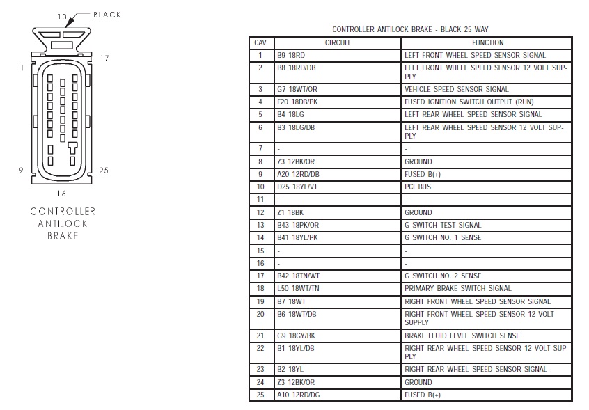
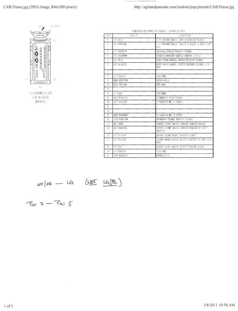
(*edit* The same WT/OR wire is pin #3 on the CAB, is that the one you spliced into?)
By the way, what year and engine are we working with here? The wiring starts to vary a little bit between...
Last edited by AgitatedPancake; 03-08-2011 at 01:04 PM.
03-08-2011, 01:15 PM
Do you have a diagram of the numbering of pins on the CAB harness so I can answer you question? I believe the WT/OR I used was in the middle, about 2/3 of the way up the harness... I'll run out and take a look at lunch.Originally Posted by AgitatedPancake
Sorry for the lack of model detail -- 1999 Limited 4.7L, 5-45rfe. Also, in pulling fuses from the ABS (since its bypassed), should I pull both of the fuses, just one? Is one of them necessary to provide the 12V power to the ABS sensor I'm using at the VSS?
03-08-2011, 01:47 PM
You probably actually need the fuses for power and signal to pass through the CAB, though I don't know for sure.
Pin #3 here
And Pin #27 here (oops the rest of the descriptions are on the next page, but you can see where pin #27 is on the plug)

03-08-2011, 02:00 PM
alright -- that helps, I'll let you know how it goes tonight! Thanks for the visuals.
03-08-2011, 02:17 PM
No prob man, let us know how it turns out! once I get a tcase with a speedo output I'll be doing this same thing to bring my speedometer back to life!
And with me having an '01 4.7, it should be the exact same as you
03-08-2011, 10:11 PM
I win!
With some help at www.mallcrawlin.com this afternoon (see above, thanks AgitatedPankake!), I get directed to this diagram, indicating I should be connecting pin #3 and pin #5 under the hood to complete the connection at the CAB:
which I stared at for a while which got me thinking, and then did some searching in my own FSM, which led me to this diagram:
See what the little Chrysler/Jeep bastids did? Some WJ's have LG/BL as a power line on the left rear ABS with the LG as the signal, some have it the other way around... It just depends on which wiring diagram you look at, and apparently which jeep you have - I had mine exactly backwards, through no fault of my own the whole freaking time
Thanks to all you guys who chimed in!
03-08-2011, 10:52 PM
badass man and thanks for coming back with all the info, this is great tech!
I'm going to have to get around to this when I upgrade my tcase...I think I may have found myself a ford NP205
03-08-2011, 11:48 PM
are you doing a 205 doubler or something? wicked.
03-09-2011, 12:37 AM
Glad to see you got it working. Nice of Chrysler to keep the wiring consistent... I should have thought of it- they changed the PCM in '04 so it would make sense that the wiring colors might change. For the sake of others doing this I hope we've covered all the variations now.
Please don't go get a 30 tooth gear though!! I think I said in one of my posts that I needed a 30 tooth gear which is most definitely wrong. I came up with that by the reasoning that my speedo was reading about 10% high so needed a gear with 10% fewer teeth. Wrong. Needs 10% more teeth <doh!> newbie mistake. Fortunately I figured it out before I blew $60 on the wrong gear.
Here's a link to the chart you need:
http://www.xjtalk.com/showthread.php?t=4398
Last edited by FearTheDentist; 03-09-2011 at 12:48 AM.
03-09-2011, 01:05 AM
That's the chart I used -- I'm currently running 33.8's on 3.73 gears -- tall I know, but it is what it is... the 38 tooth I currently have will be perfect when I regear to 4.56 in the not too distant future, though! I got a 30 tooth as a freebie from a NAXJA buddy anyways.
03-09-2011, 11:25 AM
Heh- funny. I was assuming you were going off bad info I posted elsewhere.
03-09-2011, 02:06 PM
BTW, to answer my own question asked a few posts back -- the speedo is fully operative and I have pulled both of the fuses at the under-hood power center for ABS... whereever the ABS sensor wires obtain their 12V supply, it isn't from these circuits.
03-09-2011, 02:09 PM
That's great news as well! As I want to yank the ABS controller in the future also it doesn't seem I'll be having any issues
03-09-2011, 02:32 PM
Thinking the same thing -- get some female/female brake line fittings and tie together the input/outut lines, pulling the entire CAB/pump unit... I'll let you give it a shot first.
03-10-2011, 10:47 AM
It's worth mentioning that I've been running the speedo sensor @12v since I started this thread and have not had any problems. Even though it's rated for 5v, 12v doesn't seem to be an issue.
03-10-2011, 11:54 AM
I was going to ask you if you still were... I picked up a 5v reducer from Radio Shack, so when I finalize my connections this weekend I'll likely throw it in.
| « Previous Thread | Next Thread » |
| Thread Information |
Users Browsing this ThreadThere are currently 1 users browsing this thread. (0 members and 1 guests) |